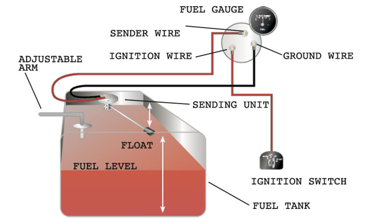
The fuel tank should be grounded and the sender wire pink should be connected to the sender terminal on the sending unit this is the correct wiring. Install the new sender by lowering the float and float arm into the tank.
Electric sending unit to fuel gauge wiring diagram.

You can find out more Diagram below
Fuel sending unit wiring diagram. The sending unit will ground through the mount screws. The older float style which uses a magnet embedded in a float that resides in a tube sending readings of how high in the tank it is floating and there is the newer style that measures electrical. One wire goes to the center pin on the tank sending unit one goes to ground and the third connects to a 12 volt source normally the ignition switch.
Remove the fuel gauge. Replace an existing fuel sender by removing the old unit. Note the direction of movement of the old float arm to assist installation.
Obtain 12 volt power from the fuse box using a standard wire and connect it to the positive terminal of the fuel gauge. There are two types of sending units. Fuel gauge sending unit wiring diagram collections of 36 fuel gauge wiring diagram chevy types of diagram.
Fuel sending unit wiring diagram volovetsfo. Automotive wiring diagram worksheet inspirationa fuel gauge sending. The fuel sending unit is responsible for what the fuel gauge on your vehicle reads.
Wire a fuel gauge by first disconnecting the old dysfunctional unit to replace it with a new one. Electric fuel sender wiring diagram wire center wiring diagram. Position new unit above tank aligning screw hole pattern in the mounting flange with hole pattern in top of tank.
The fuel gauge reads the resistance to ground check the wires on the back of the gauge pink to s terminal and black to g terminal.


0 comments:
Post a Comment