The emergency ballast wiring guide this document has been customized to contain a wide library of individual dia grams for various installation applications. Collection of electronic ballast wiring diagram.
A wiring diagram is a simplified standard pictorial representation of an electrical circuit.

You can find out more Diagram below
Electronic ballast wiring diagram. If a diagram cannot be found within this selection consult customer service. Series vs parallel ballasts and wiring when a series ballast rapid start operates multiple lamps and one lamp fails the circuit is opened and the other lamps will not light. The diagrams are categorized primarily according to the number of lamps in the.
This is electronic ballast for cfl compact fluorescent lamp circuit using ir2156. Commercial cfls use a separate ballast. 1 turn off the breaker for the circuit governing the.
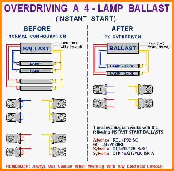
Newer electronic ballasts are usually wired in parallel except for rapid start programmed start and dimmable ballasts. Instant start electronic ballasts use a high starting voltage about 600 volts to start very quickly less than 01 seconds. Ballasts have a wiring diagram to show how they connect to the lampholders.
There are four basic types of fluorescent ballasts. There is no preheating of the electrodes for the. Follow the colore coded wiring diagram was the recommendation yet after connecting all like colors on the new ballast to the fixture all i got was a delayed dim light at the base of each fluorescent bulb.
It shows the components of the circuit as streamlined shapes as well as the power and also signal connections between the gadgets. It reveals the components of the circuit as streamlined shapes and also the power and also signal connections between the devices. If you have an older fixture you can switch from a magnetic ballast to an electronic ballast in a few minutes with some basic hand tools.
Variety of 2 lamp t12 ballast wiring diagram. So how to wire the new ballast to my fixture so it works. It reveals the parts of the circuit as simplified forms as well as the power and also signal links in between the devices.
I suspect the wiring is not as simple as described. Electronic ballast magnetic ballast universal lighting technologies is a subsidiary of panasonic lighting americas a member of the panasonic corporation eco solutions company 2 lamp rapid start to 2 lamp electronic instant start retrofit wiring diagrams notes. A wiring diagram is a simplified standard photographic depiction of an electrical circuit.
This is applicable for 2 lamp t12 rapid start to a 2 lamp electronic t8 system. Variety of 2 lamp t8 ballast wiring diagram. A wiring diagram is a streamlined standard pictorial representation of an electric circuit.
The ir2156 contains a high voltage half bridge gate driver with a state diagram and programmable oscillator to make a full ballast control ic.


0 comments:
Post a Comment