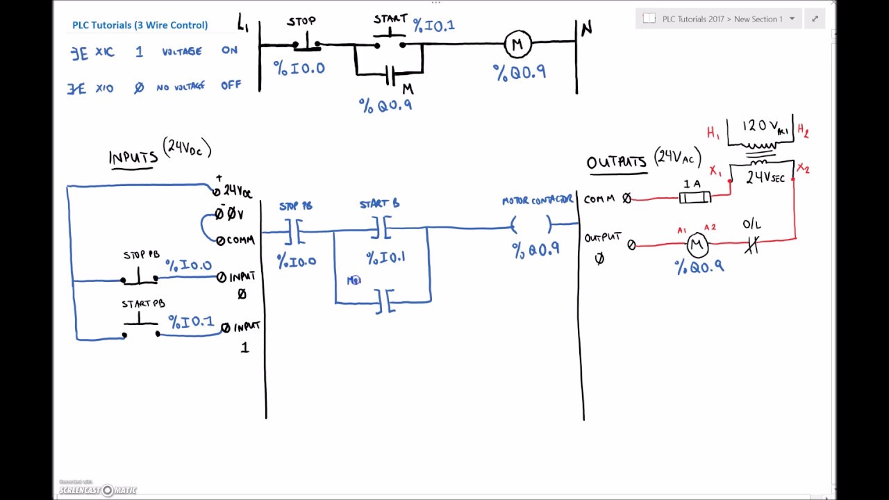
In this motor control circuit example we have a problem. These symbols are standard and.
Everything inside the dashed box happens inside the plc.
You can find out more Diagram below
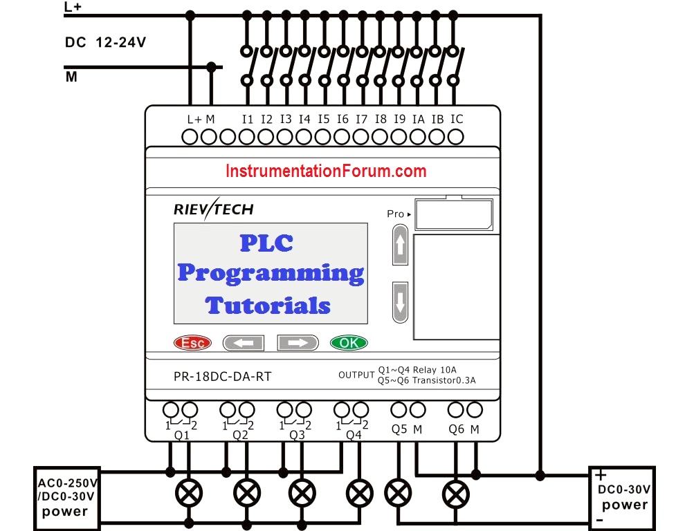
Plc wiring diagram tutorial. Upgrading a machine to plc control may seem like a daunting task. Plc program example with toggle or flip flop function see more. Plc wiring 35 in the example there are two inputs one is a normally open push button and the second is a temperature switch or thermal relay.
However if you take your time and learn how to convert a basic wiring diagram to a ladder logic plc program it can be an easily achievable task. Discover ideas about control system. In an industrial setting a plc is not simply plugged into a wall socket.
The picture to the right shows an example of what the wiring of a plc with 4 inputs would look like. A filling a tank to a predetermined level b agitating the liquid for 30 minutes c draining the tank for use in another part of process does the ladder logic schematic that follows perform. This section on programmable logic controllers.
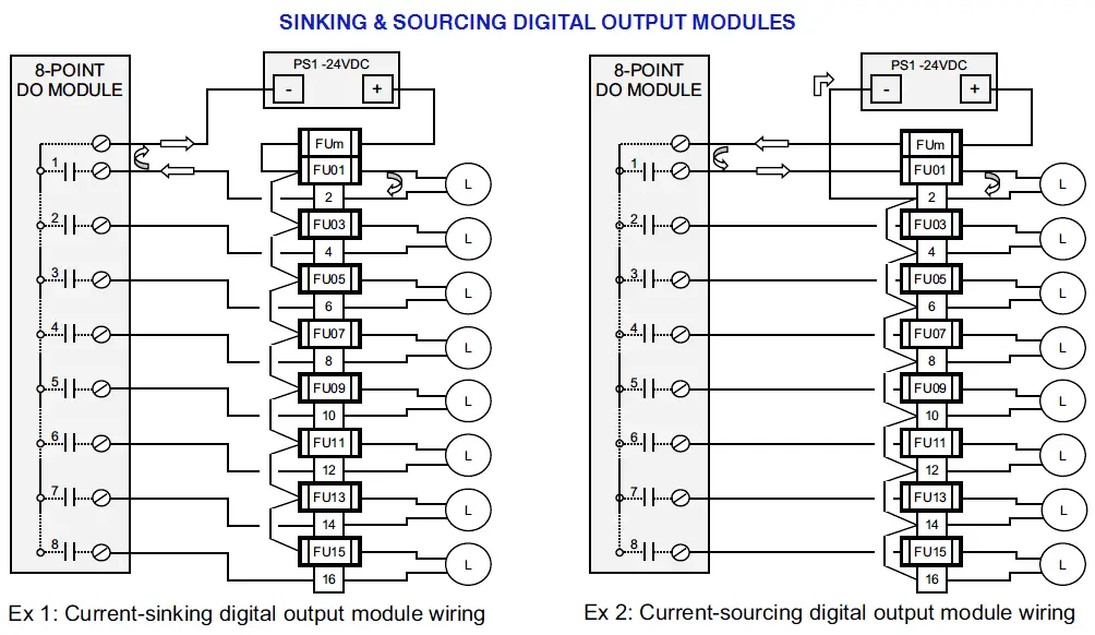
Programmable logic controllers plc chapter 6 ladder logic. In order to increase io points on plcs without increasing the number of connections commons are used. This video describes how to wire your controller.
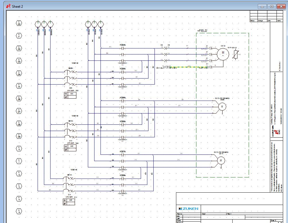
Oct 28 2019 plc control panel wiring diagram on within. Transformers to step down ac supply voltages to lower levels. Electrical ladder diagrams and jic wiring symbols.
The electrical design for each machine must include at least the following components. In this video the connection to the wiring of siemens plc s7 200 has been done with an easy way. Oct 28 2019 plc control panel wiring diagram on within.
Shows which direction power flows through the circuit. Awesome motor starter wiring diagram images within allen bradley throughout plc. Ladder diagram example a manual mixing operation is to be automated using sequential process control methods.
Electrical wiring diagrams of a plc panel. If the input wiring for x2 the stop switch were to fail open there would be no way to stop the motor. Wiring on the device or devices being controlled.
As an introduction to ladder diagrams consider the simple wiring diagram for an electrical circuit in figure 1athe diagram shows the circuit for switching on or off an electric motor. The process composed of three steps. Introduction to plc ladder diagrams.
Plc wiring 32 quantities of io and limited abilities but costs will be the lowest.


.png?resize=622%2C437&ssl=1)


0 comments:
Post a Comment