Circuitry layouts are made up of 2 things. A typical 0 10v wiring diagram is shown below.
If the light output can only be dimmed from 100 down to 10 there must be a switch or relay available to kill power to the system and turn the light.

You can find out more Diagram below
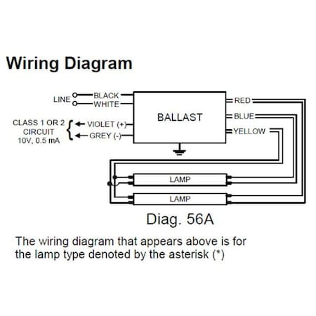
0 10v dimming ballast wiring diagram. Where to use a 0 10v dimmer. Wiring diagram using relay 0 10 v ballastdriver white white red red red white blue gray graygray red red purple purple purple blue white black black 0 10 v ballastdriver neutral. 0 10v class 1 and class 2 wiring overview 0 10v ballasts and drivers are connected together by a 2 wire low voltage bus that is suitable for class 1 or class 2 wiring installations.
It shows the elements of the circuit as simplified shapes and also the power and also signal connections in between the devices. Wiring diagram using a power pack 010 v ballast driver neutral red red redwhite red white ground blue black black neutral line hot pp dvpp 347h class 2 only switched hot dimming with on off control for drivers which support dim to off capability power wiring not shownsee lighting device for wiring blue redwhite red wiring. In many cases the dimming range of the power supply or ballast is limited.
0 10v dimming ballast wiring diagram just whats wiring diagram. Collection of 0 10 volt dimming wiring diagram. Variety of 0 10v dimming ballast wiring diagram.
A wiring diagram is a type of schematic which makes use of abstract photographic symbols to reveal all the affiliations of components in a system. A 0 10v dimmer is considered analog dimming and all usai 0 10v dimming options are considered to be sink type dimming. The diva 0 10v preset dimmer provides dimming control of 0 10v led drivers uorescent ballasts and hid ballasts.
Specification submittal page. It shows the elements of the circuit as streamlined forms and the power and signal connections between the devices. 0 10v dimming wiring diagram 0 10v dimmer switch leviton ip710 lfz or equal for other types of dimming control systems consult controls manufacturer for wiring instructions switched hot black switched hot red typical low voltage dimming wires purple gray typical electrical panel hot black typical 120v or 277v 60 hz neutral white.
A wiring diagram is a streamlined standard photographic representation of an electric circuit. A wiring diagram is a simplified standard photographic depiction of an electric circuit. This application note explains how both class 1 and 2 wiring are made and how they both meet national electric code nec regulations.
With the rise of led in recent years 0 10v dimming has adapted to become a reliable led dimming control method and has become increasingly. Our standard 0 10v dimming driver option is often provided standard check spec sheets and dims down to 10 at minimum light level. 0 10v dimming was first developed for and is still used as a standard method of controlling fluorescent fixtures using light intensity controlling dimming ballasts.
Often dimming ballasts and dimming led power supplies use 0 10v control signals to control dimming functions. Symbols that stand for the components in the circuit and also lines that stand for.


0 comments:
Post a Comment