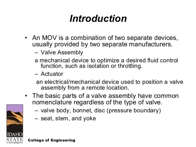
The function of the power supply is to supply the energy required to operate the valve to which the actuator is attached. Condition lost phase or jammed valve protection.
Valve so the flow direction arrow on the side of the valve indicates the direction of the process flow.

You can find out more Diagram below
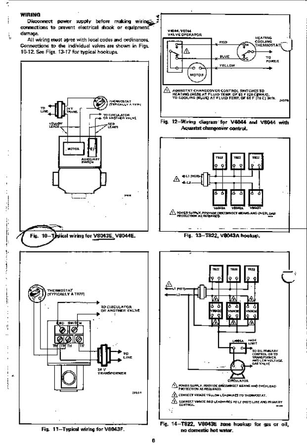
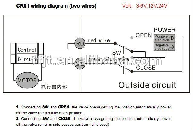
Motor operated valve wiring diagram. The wiring diagram selector returns standard iq3iqt3 range wiring diagrams only. 112 wiring 25 113 valve interface 25 114 design life and endurance 25 115 diagnostic features 26 116 factory test 26 117 conduit entries 26 118 european directives 26 12. Motor operated valve wiring diagram can be a variety of can be 2 lines 3 lines 4 lines can also be connected with a feedback signal line 2 lines can also be with ground wire.
Close this site uses cookies. Standard wiring diagram 9 optional features wiring diagrams 10. College of engineering typical wiring diagram.
Although there are many sources of power the figure 5 1 typical wiring diagram assumption is made that 240 volt alternating. Motor operated valve wiring diagram. Fisher d4 valve with gen 2 easy drive actuator wiring diagram field wiring connections motor gearbox assy ge84238 controller power and control terminal ge47302 7 top view controller.
Some of the cookies we use are essential for parts of the site to operate and have already been set. Wiring diagrams m c w bulletin 600 bulletin 600 manual starting switches are designed for starting and protecting small ac and dc motors rated at 1 hp or less where undervoltage protection is not needed. Circuits for both torque and limit controlled valves.
Wiring diversification according to the customer equipment voltage is different line number is different provide different wiring mode. Motor thermal protec tion may be bypassed for critical esd applications in non hazardous or special service locations. On this website we recommend many designs abaout motor operated valve wiring diagram that we have collected from various sites home design and of course what we recommend is the most excellent of design for motor operated valve wiring diagramif you like the design on our website please do not hesitate to visit again and get inspiration from all the.
0421 e112 motor operated valves course 05 mov controls slides. Wiring configurations for the mx and qx 28 121 mxqx terminal block 28 122 wiring diagram configurator 28 13. Wiring diagrams do not show the.
Actuator can be operated in either direction. They are operated by a toggle lever mounted on the front of the switch. For specials or if you cant find what you want please contact rotork.
Describe the electrical and mechanical components. Rotork wiring diagram selector. Mx and qx wiring diagrams 29 14.


0 comments:
Post a Comment